Design Calculation Of Reflux Condenser
Fix It Driver Serial Number. Shell and tube condenser design (CnD) software is a tool that demonstrates the thermal design calculations for shell and tube condensers.

• The Spray Condenser. The coolant is sprayed, using nozzles, into a vessel to which the vapor is supplied. This is shown schematically in. It is important that the spray nozzles and vessel are designed to produce a fine spray of liquid (to give a large interfacial area for heat transfer), and a long enough residence time of liquid droplets in the vessel. • The Baffled Column. This is similar to the spray condenser, except that the coolant is directed to flow over a series of trays in a column (see ).
The vapor is supplied to the bottom of the column. It has the advantage of countercurrent flow of vapor and coolant, though care must be taken to avoid flooding.
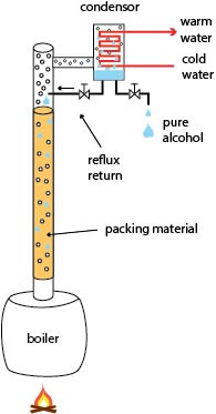
(Flooding is an unstable condition when the vapor flow is such that the downward flow of condensate is interrupted and held up.) • The Packed Column. A packed column may consist of tightly-packed metal rings to increase the interfacial area for heat transfer. Liquid is supplied to the top of the column and vapor is supplied to the bottom. The disadvantage of this type of condenser is that the pressure drop is higher than in other types of direct-contact condenser. • The Jet Condenser. This is a device in which a jet of liquid is directed into a vapor stream, usually with the objective of desuperheating the vapor. A jet of liquid is injected into a pipeline carrying vapor via a small bore pipe and a nozzle located at the center line.
The liquid is usually injected in counterflow to the vapor. • The Sparge Pipe. The sparge pipe consists of a pipe with holes for injecting bubbles of vapor into a pool of liquid. This is a simple method of condensing a vapor, but there are practical problems associated with generating a good distribution of bubbles of small size, which are required for efficient heat transfer.